Advanced Technology

Direct Drive inverters — a Sunvertec Innovation

Sunvertec’s Direct Drive inverter technology has many advantages making it ideal for incorporating directly into battery storage and for solar PV power conversion. Direct Drive and it’s addition to Sunvertec’s SONEX high power AC battery storage systems, represent more than 5 years of research and development.

How a waveform is made

Direct Drive splits the task of converting power across multiple units that work together. These units are connected to solar panels or batteries and they operate in a synchronised fashion to produce pure-AC.

By splitting the hard task of converting power in to multiple simpler, smaller tasks the total size and weight of the inverter system is considerably reduced.

Overview of how Direct Drive works to create a waveform

A pure sine wave is created by series connected modules. These series connected modules add voltages together to create a total voltage.

Unlike traditional inverters that create a total mains AC voltage from a single DC power source, Direct Drive switches low voltage DC power sources and a Distriverter corrects the waveform to create the pure sine wave.

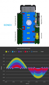
Direct Drive Waveform Creation

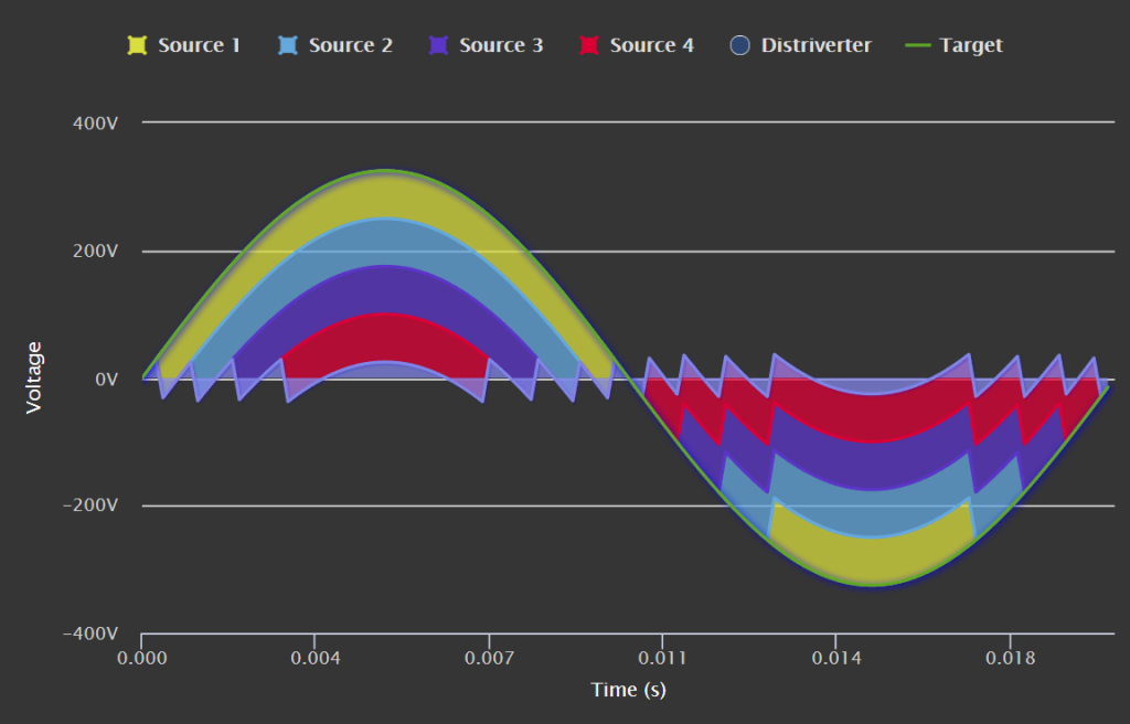
Click the image for an interactive view of how the waveform is created

Note the “staircase” produced by the series connected Inverter Optimisers. Just 4 Inverter Optimisers are required to produce mains level voltages, with the 5th (of the minimum system) aiding in flexibility for shaded systems and providing a level of redundancy.

Note also the few changes of state required, aiding in efficiency, and the small error between the staircase and the target waveform.

A 5kW Direct Drive inverter takes up about 3 litres of space. With competing inverter solutions being in the 30-40L range, it shows just how advantageous Sunvertec’s approach is. With smaller size comes lower weight, simpler electronics, and lower prices.

How is the waveform created? A Technical Description

For the technically minded … especially for those with an electronics background,  a technical description of our Direct Drive inverter follows. See the video for an easier explanation.

Images

The images to the right are taken from Sunvertec’s SONEX implementation of Direct Drive Technology. Solar PV is similar but separated into individual optimisers that each have one or more MPPT inputs. The Distriverter has similar components for both Solar PV and SONEX implementations.

The Inverter Optimiser

The Inverter Optimiser, or “switcher”, is the core component of Xenos and Sonex. The Inverter Optimiser draws a controlled amount of current from its DC sources at the source’s maximum power point or moves an average current from storage devices.

For solar PV and selected SONEX implementations, a DC-DC converter moves charge between the Optimiser and power source. The Inverter Optimiser stores this charge into on-board local energy storage devices. Significantly, the DC-DC converter is extremely efficient as it typically does not alter the input voltage much at all, allowing each Inverter Optimiser to operate in excess of 99% efficiency. This gives them huge power handling for their compact size. The local energy storage devices effectively “float” a certain charge level, experiencing low ripple currents and temperatures, giving them an ultra long life.

The Distriverter

The Distriverter is at the heart of Direct Drive technology. The Distriverter creates the pure sine wave, commanding Optimisers to switch forwards or reverse to support it in creating the waveform.

When commanded by the local Distriverter, an Inverter Optimiser places its energy storage across a series connection in either a positive or negative direction via the use of very low resistance MOSFETs. After a small period, the Distriverter returns the Inverter Optimiser to its bypassed state (the default state).

By switching between these three states, positive, bypassed, and negative, Inverter Optimisers can generate a “staircase” approximation of any low frequency signal, such as a mains signal. State changes occur infrequently (< 400Hz), meaning that switching losses involved in producing this “staircase” are negligible.

Whilst each Inverter Optimiser is only a low voltage part (typically < 80V), the series connection “adds” the output of each Inverter Optimiser to the next such that high total voltages can be produced. Just as two 12V batteries produce 24V when connected in series, strings of Inverter Optimisers (and their ability to switch “positive”, “negative” or “bypassed”) are able to output controlled voltages far above that of an individual unit.

Direct Drive operation:

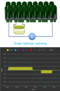
  1. Firstly, a single Optimiser is shown stepping high and low
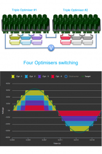
  2. Next the graph shows a staircase created by four Optimisers switching
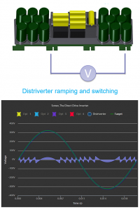
  3. The Distriverter waveform looks like a chopped up sine wave as it both ramps and steps
  4. and lastly, all devices are series connected creating a perfect sine wave

Integrating with the grid

The Distriverter controls power flow into and out of the grid. It does this by sensing it’s series current and adjusting the output voltage of the Distriverter. SONEX with Direct Drive technology operates in both this mode and stand along, powering a circuit.

  • While controlling the current, SONEX operates as a Current Source Inverter (CSI).
  • While not connected to the grid and operating as a stand along power source, SONEX operates as a Voltage Source Inverter (VSI).